8.1.8.2. KENO VI Shape Descriptions
The geometry shapes allowed in KENO-VI geometry description are:
CONE, CUBOID, CYLINDER, DODECAHEDRON, ECYLINDER, ELLIPSOID, HEXPRISM, HOPPER, PARALLELEPIPED, PPIPED, PENTAGON, PLANE, QUADRATIC, RHEXPRISM, RHOMBOID, SPHERE, WEDGE, XCYLINDER, XPPLANE, YCYLINDER, YPPLANE, ZCYLINDER, ZPPLANE
- CONE
specifies a body consisting of one nappe of a right circular cone. It is defined by specifying the top radius of the cone, Rt, the Z coordinate of the top face, Zt, the bottom radius of the cone, Rb, and the Z coordinate of the bottom face, Zb. Fig. 8.1.211 shows the correct input sequence for a cone.
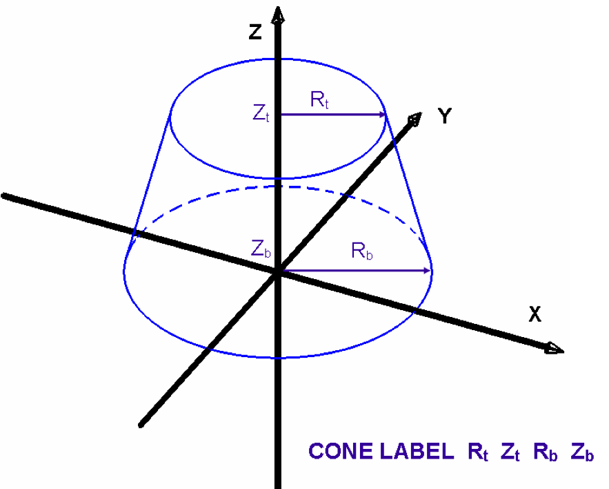
Fig. 8.1.211 Example of cone construction.
- CUBOID
specifies a rectangular parallelepiped. It is defined by specifying the +X dimension, -X dimension, +Y dimension, -Y dimension, +Z dimension, -Z dimension. It is perpendicular to the X, Y, and Z axes unless otherwise specified by the option geometry modification data. Fig. 8.1.212 shows the correct input sequence for a cuboid.
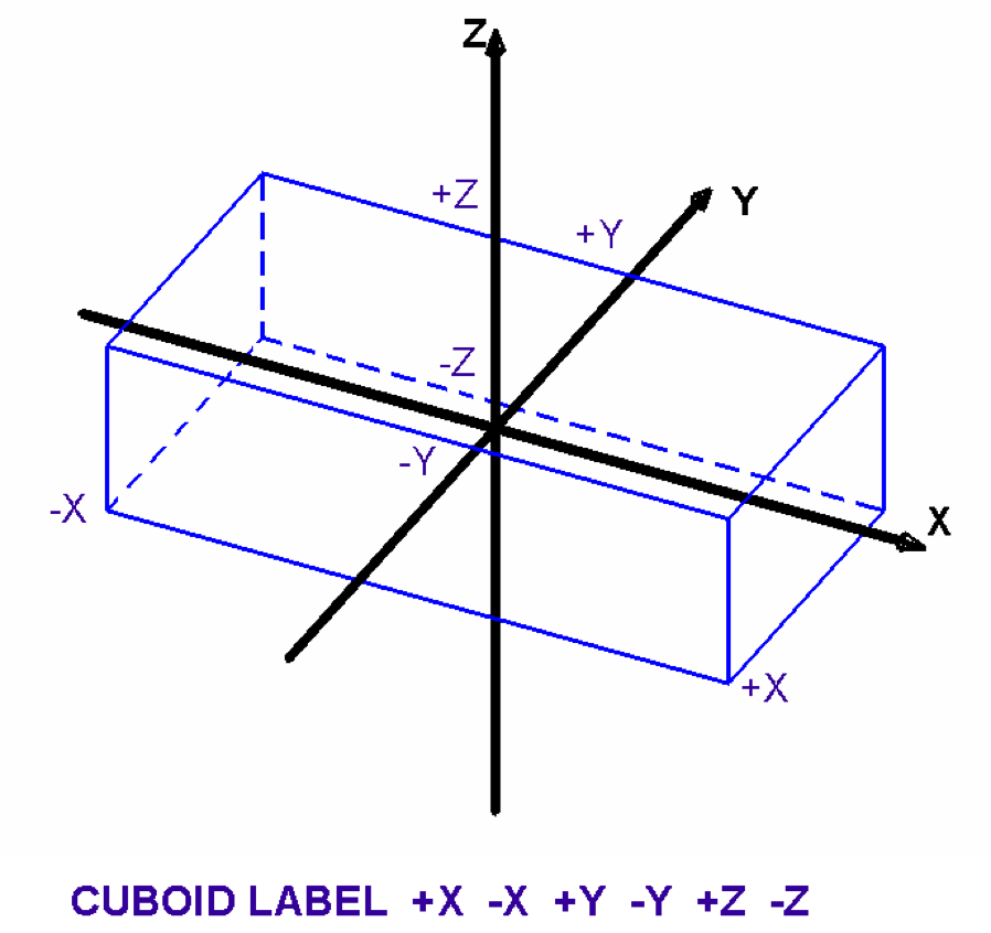
Fig. 8.1.212 Example of cuboid construction.
- CYLINDER
specifies a right circular cylinder. It is defined by specifying the radius of the cylinder, R, the Z coordinate of the top face, Zt, and the Z coordinate of the bottom face, Zb. Its centerline must lie on the Z axis, unless otherwise specified by the optional geometry modification data. Fig. 8.1.213 shows the correct input sequence for a cylinder.
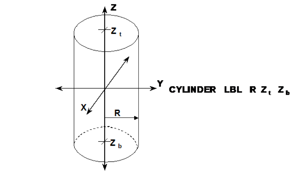
Fig. 8.1.213 Example of cylinder construction.
- DODECAHEDRON
specifies a body whose surface consists of 12 rhombuses of the same size and shape. It is defined by specifying the radius of the inscribed sphere, R. It is centered on the origin in a fixed orientation unless otherwise specified by the optional geometry modification data. Fig. 8.1.214 shows the correct input sequence for a dodecahedron.
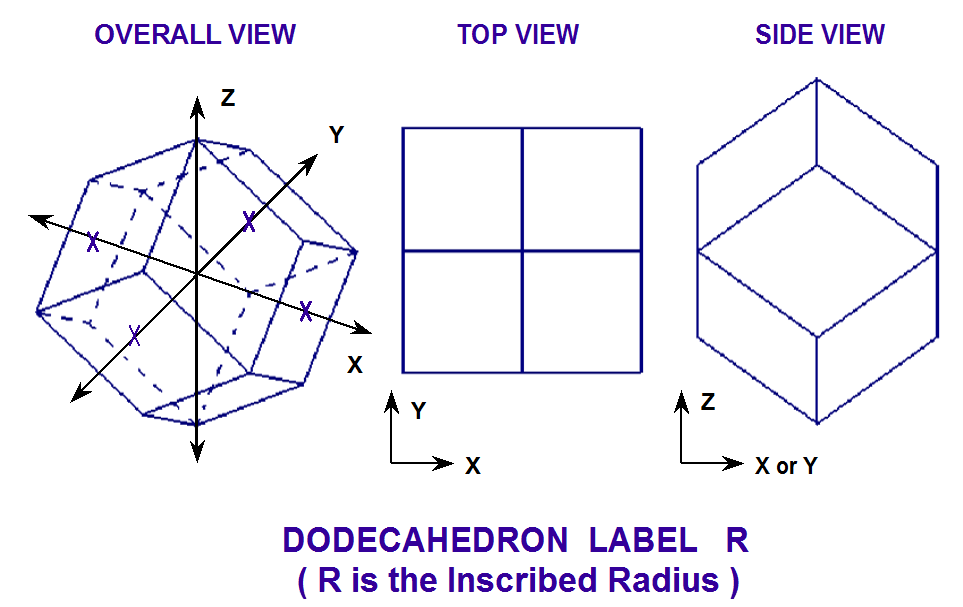
Fig. 8.1.214 Example of dodecahedron construction.
- ECYLINDER
specifies a right cylinder with an elliptical cross section. It is defined by specifying the semiradius along the X-axis, Rx, the semiradius along the Y-axis, Ry, the Z coordinate of the top face, Zt, and the Z coordinate of the bottom face, Zb. Its centerline must lie on the Z axis, unless otherwise specified by the optional geometry modification data. Fig. 8.1.215 shows the correct input sequence for an elliptical cylinder.
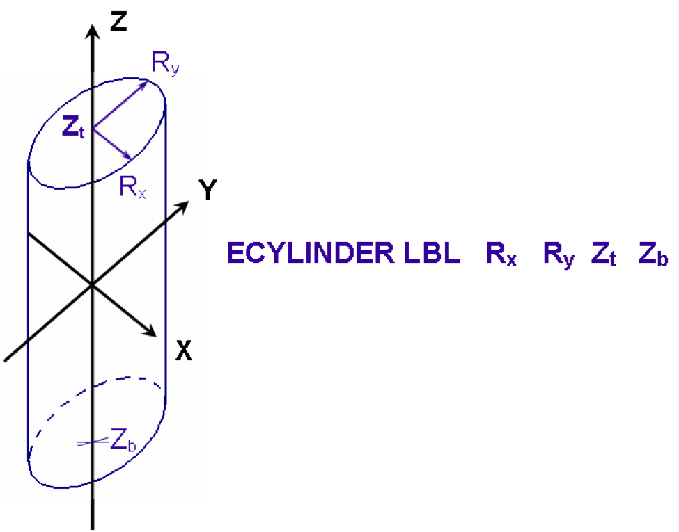
Fig. 8.1.215 Example of elliptical cylinder construction.
- ELLIPSOID
specifies a body whose cross-section slices parallel to each of the coordinate axes are ellipses. It is defined by specifying the semiradius along the X-axis, Rx, the semiradius along the Y-axis, Ry, and the semiradius along the Z-axis, Rz. It is centered about the origin, unless otherwise specified by the optional geometry modification data. Fig. 8.1.216 shows the correct input sequence for an ellipsoid.
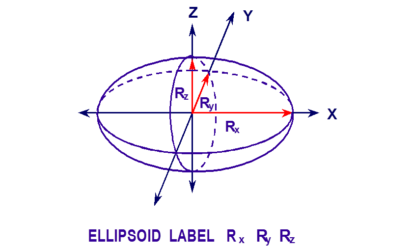
Fig. 8.1.216 Example of ellipsoid construction.
- HEXPRISM
specifies a body whose top and bottom faces are hexagons that have the same orientation and are perpendicular to the Z axis. It is defined by specifying the inscribed radius, R, the Z coordinate of the top face, Zt, and the Z coordinate of the bottom face, Zb. Fig. 8.1.217 is an example input for a hexprism.
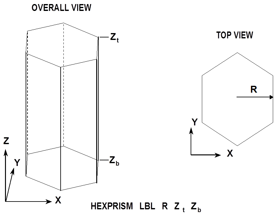
Fig. 8.1.217 Example of hexprism construction.
- HOPPER
specifies a body whose top and bottom faces are rectangular parallelepipeds centered about the Z-axis and parallel to the X and Y axes. It is defined by specifying the half-length of the top face along the X-axis, Xt, the half-length of the top face along the Y-axis, Yt, the Z coordinate of the top face, Zt, the half-length of the bottom face along the X-axis, Xb, the half-length of the bottom face along the Y-axis, Yb, and the Z coordinate of the bottom face, Zb. Its centerline must lie on the Z axis unless otherwise specified by the optional geometry modification data. Fig. 8.1.218 shows the correct input sequence for a hopper.
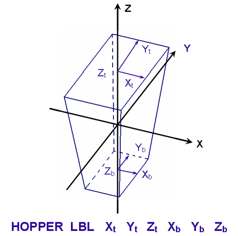
Fig. 8.1.218 Example of hopper construction.
- PARALLELEPIPED or PPIPED
is a body with six faces composed of parallelograms, whose opposing faces are parallel. It is defined by specifying the length of the faces in the X direction, XDIST, the length of the faces in the Y direction, YDIST, the length of the faces in the Z direction, ZDIST, the angle between the X-face and the Y-axis, PSI, the angle between the Y-face and the Z-axis, THETA, and the angle between the projection of the top corner nearest the Z-axis onto the X-Y plane and the X-axis, PHI. The bottom face must lie on the X-Y plane at Z = 0 with a corner at the origin unless otherwise specified by the optional geometry modification data. Fig. 8.1.219 shows the correct input sequence for a parallelepiped. The angles psi, theta, and phi must be in the range 0 to 90\(^{\circ}\).
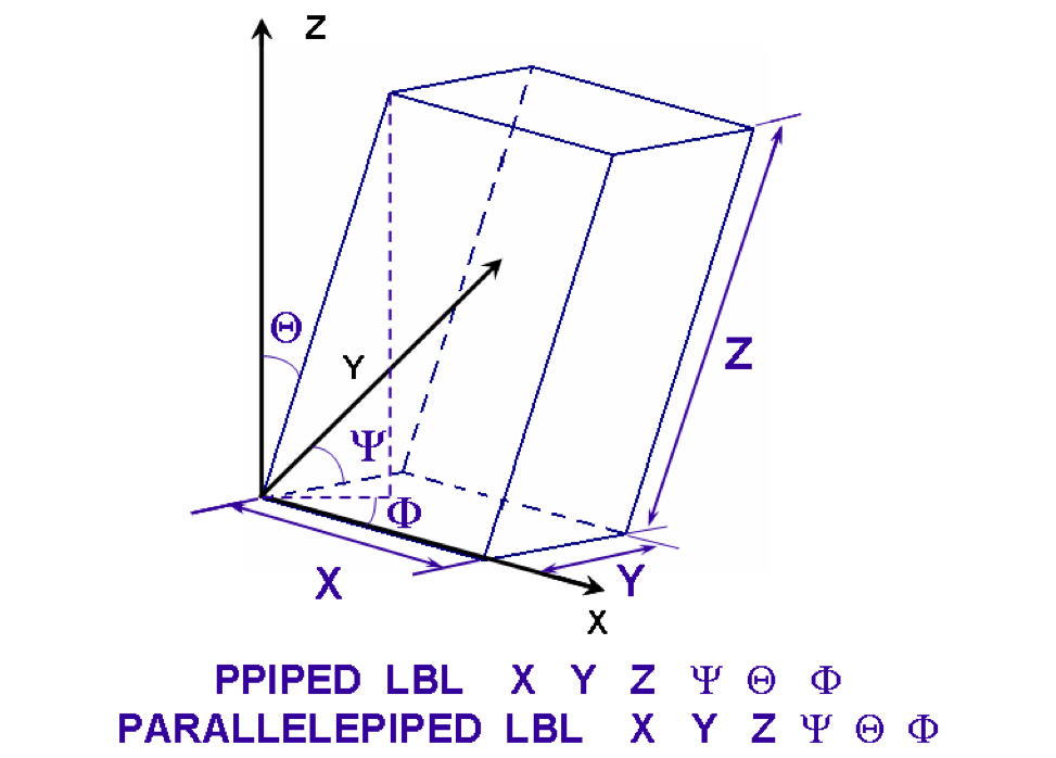
Fig. 8.1.219 Example of parallelepiped construction.
- PENTAGON
specifies a body whose top and bottom faces are pentagons that have the same orientation and are perpendicular to the Z axis. It is defined by specifying the inscribed radius, R, the Z coordinate of the top face, Zt, and the Z coordinate of the bottom face, Zb. Fig. 8.1.220 is an example input for a pentagon.
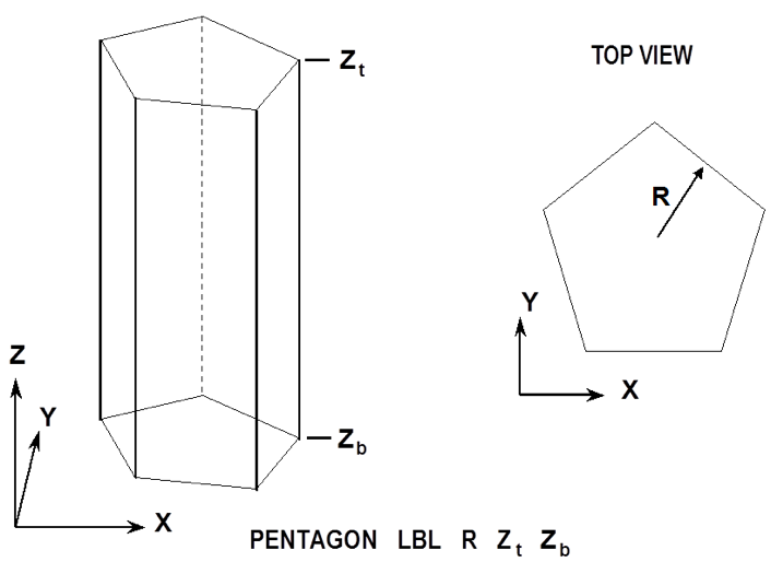
Fig. 8.1.220 Example of pentagon construction.
- PLANE
is a surface where any two points can be connected by a straight line entirely contained within a plane that divides all space into two regions. The positive side of the plane is the side the normal points to or where the equation aX + bY + cZ + d > 0. It is defined by specifying the coefficients of the equation aX + bY + cZ + d = 0 using the keywords XPL=a, YPL=b, ZPL=c, and CON=d. Only the nonzero coefficients of the equation need to be specified. Fig. 8.1.221 shows the correct input sequence for a plane.
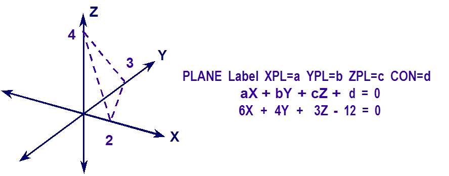
Fig. 8.1.221 Example of plane construction.
- QUADRATIC
specifies a surface using a quadratic equation of the form:
aX2 + bY2 + cZ2 + dXY + eXZ + fYZ + gX + hY + iZ + j = 0.
It is defined by specifying the coefficients of the above equation using the keywords AQU=a, BQU=b, CQU=c, DQU=d, EQU=e, FQU=f, GQU=g, HQU=h, IQU=i, and JQU=j. Only the nonzero coefficients of the equation need to be specified.
- RHEXPRISM
specifies a body whose top and bottom faces are rotated hexagons that have the same orientation and are perpendicular to the Z axis. It is defined by specifying the inscribed radius, R, the Z coordinate of the top face, Zt, and the Z coordinate of the bottom face, Zb. Fig. 8.1.222 is an example input for a rotated hexprism.
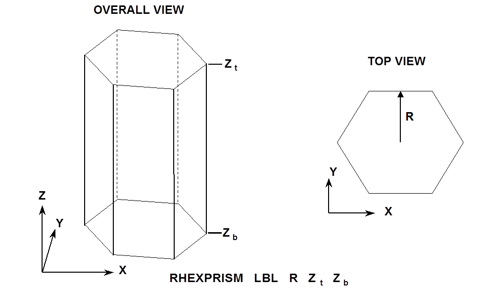
Fig. 8.1.222 Example of rotated hexprism construction.
- RING
is a body composed of the space between 2 concentric cylinders. It is defined by specifying the radius Rin of the inner cylinder and Rout of the outer cylinder, and the coordinate Zt of the top and Zb of the bottom of the annulus. Its center line lies on the Z axis unless specified by the optional geometry modification data. Fig. 8.1.223 shows the correct input sequence for a ring.
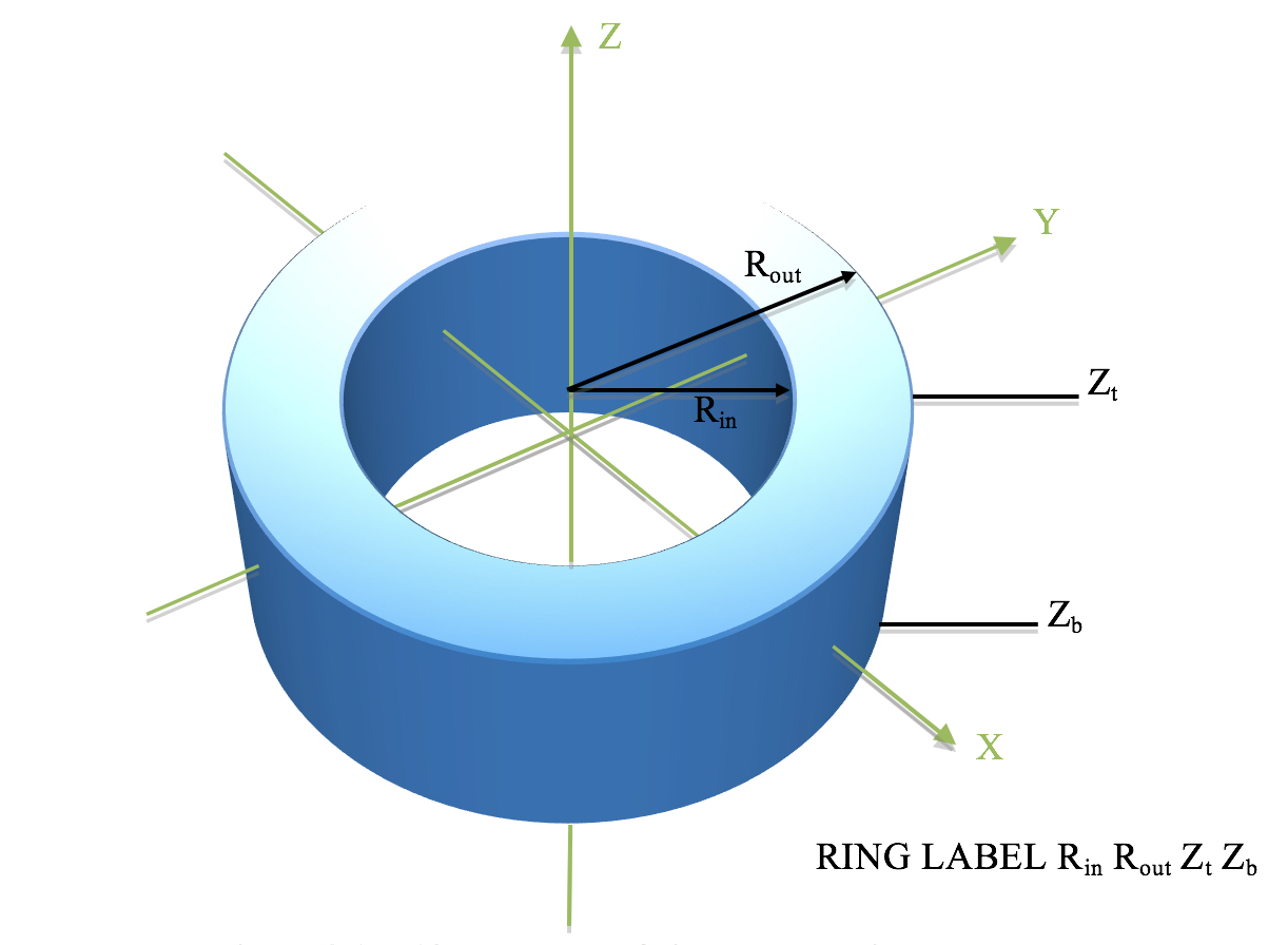
Fig. 8.1.223 Example of ring construction.
- RHOMBOID
is a body composed of six identical faces, each one a rhombus. It is defined by specifying the length of the edge of the base along the X-axis, DX and the angle between Y edge of the base and the Y-axis, \(\Psi\). Its base is in the XY plane at Z = 0, with a corner at the origin unless otherwise specified by the optional geometry modification data. Fig. 8.1.224 shows the correct input sequence for a rhomboid.
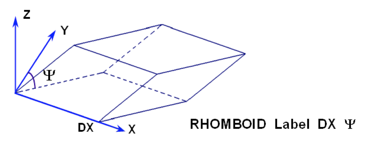
Fig. 8.1.224 Example of rhomboid construction.
- SPHERE
specifies a sphere. It is defined by specifying the radius, R. It is centered about the origin, unless otherwise specified by the optional geometry modification data. Fig. 8.1.225 shows the correct input sequence for a sphere.
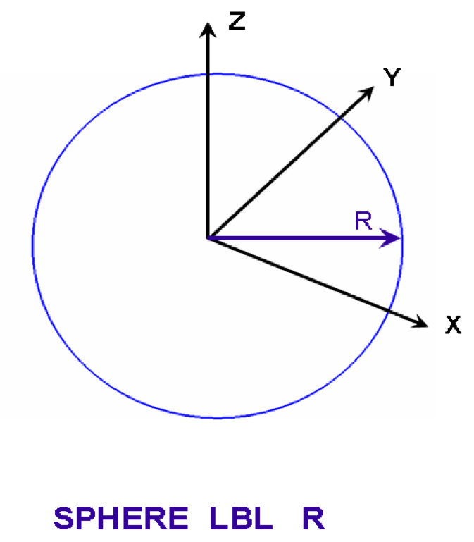
Fig. 8.1.225 Example of sphere construction.
- WEDGE
is a right-triangular prism having five faces. The two ends are triangles, and the three sides are rectangles. It is defined by specifying the length of the base along the X-axis, XBASE, the X and Y coordinate where the other two sides meet, Xpt and Ypt, and the length along the Z-axis, ZLNG. One side is in the XZ plane at Y = 0, and the bottom face is in the XY plane at Z = 0, with a corner at the origin unless otherwise specified by the optional geometry modification data. Fig. 8.1.226 shows the correct input sequence for a wedge.
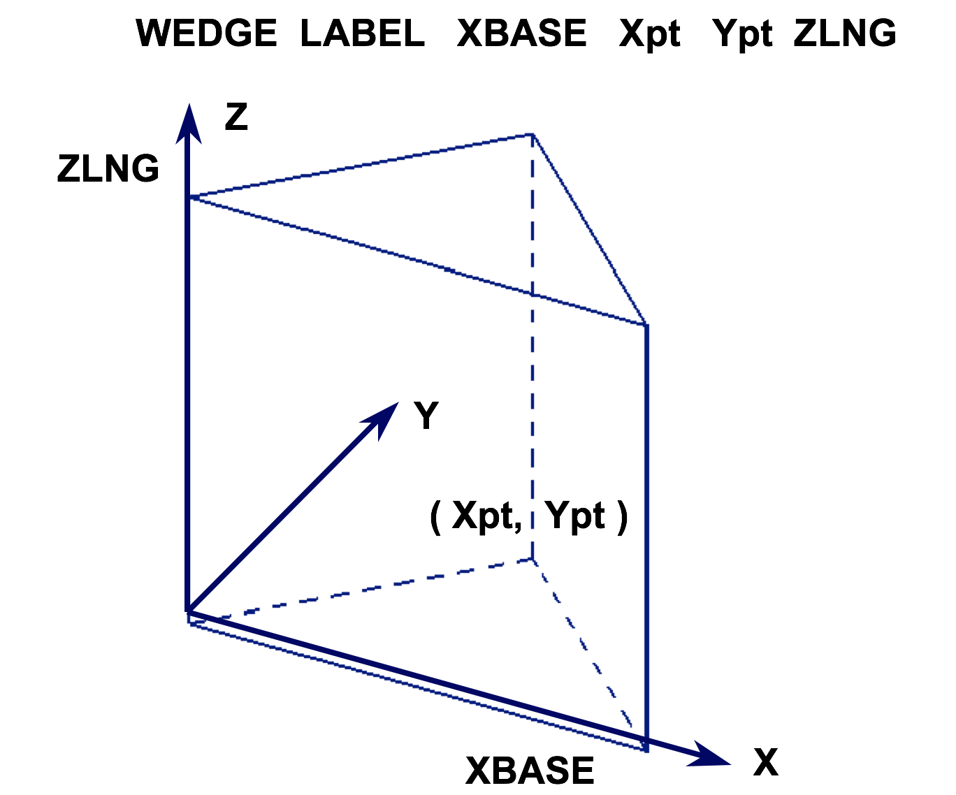
Fig. 8.1.226 Example of wedge construction.
- XCYLINDER
specifies a right circular cylinder oriented about the X-axis. It is defined by specifying the radius of the cylinder, R, the X coordinate of the top face, X t, and the X coordinate of the bottom face, X b. Its centerline must lie on the X axis, unless otherwise specified by the optional geometry modification data. Fig. 8.1.227 shows the correct input sequence for a cylinder.
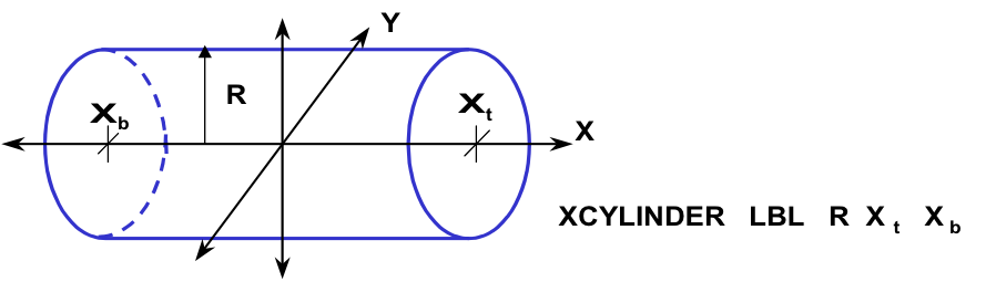
Fig. 8.1.227 Example of xcylinder construction.
- XPPLANE
is a set of flat parallel surfaces where any two points in one of the surfaces can be connected by a straight line entirely contained within that surface. These surface planes divide space into three sections; one section between the two planes which is considered inside the surfaces, one section on the negative side of the negative plane which is considered outside the surfaces, and one section on the positive side of the positive plane which is considered outside the surfaces. The set of parallel planes are defined by the keyword XPPLANE, which places the planes perpendicular to the X-axis, the X-intercept between the more positive plane and the X-axis (X+) and the X-intercept between the more negative plane and the X-axis (X-). Fig. 8.1.228 shows the correct input sequence for the set of paired planes.
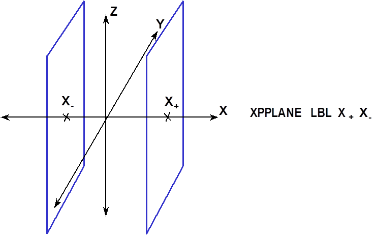
Fig. 8.1.228 Example of x-paired plane construction.
- YCYLINDER
specifies a right circular cylinder oriented about the Y-axis. It is defined by specifying the radius of the cylinder, R, the Y coordinate of the top face, Yt, and the Y coordinate of the bottom face, Yb. Its centerline must lie on the Y axis, unless otherwise specified by the optional geometry modification data. Fig. 8.1.229 shows the correct input sequence for a cylinder.
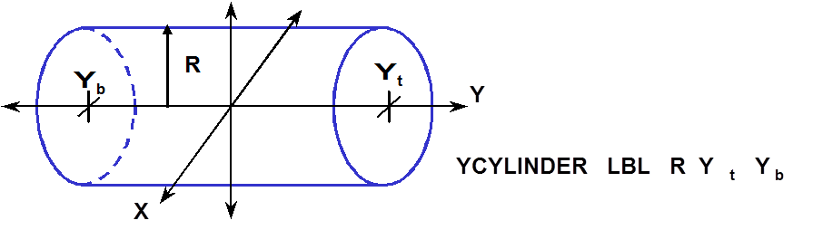
Fig. 8.1.229 Example of ycylinder construction.
- YPPLANE
is a set of flat parallel surfaces where any two points in one of the surfaces can be connected by a straight line entirely contained within that surface. These surface planes divide space into three sections; one section between the two planes which is considered inside the surfaces, one section on the negative side of the negative plane which is considered outside the surfaces, and one section on the positive side of the positive plane which is considered outside the surfaces. The set of parallel planes are defined by the keyword YPPLANE, which places the planes perpendicular to the Y-axis, the Y-intercept between the more positive plane and the Y-axis (Y+) and the Y-intercept between the more negative plane and the Y-axis (Y-). Fig. 8.1.230 shows the correct input sequence for the set of paired planes.
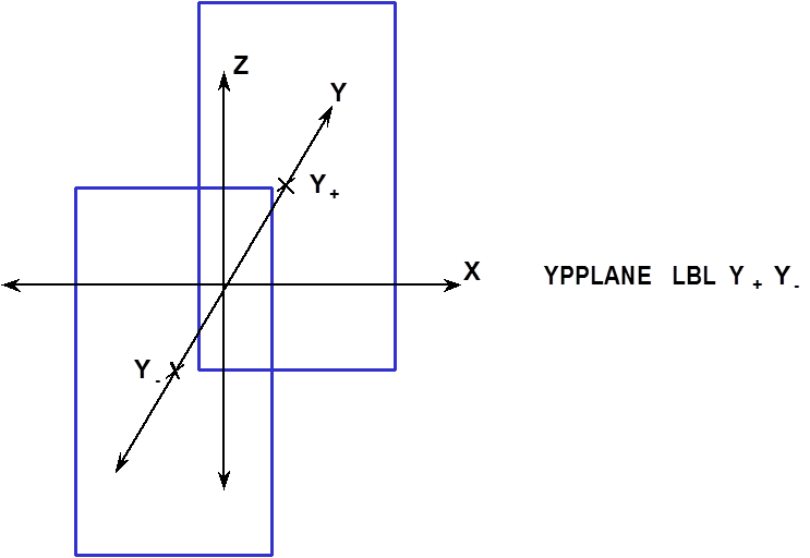
Fig. 8.1.230 Example of y-paired plane construction.
- ZCYLINDER
specifies a right circular cylinder oriented about the Z-axis. It is defined by specifying the radius of the cylinder, R, the Z coordinate of the top face, Z t, and the Z coordinate of the bottom face, Z b. Its centerline must lie on the Z-axis, unless otherwise specified by the optional geometry modification data. The keyword ZCYLINDER is the same as CYLINDER. It is included to be consistent with the XCYLINDER and YCYLINDER keywords. Fig. 8.1.231 shows the correct input sequence for a zcylinder.
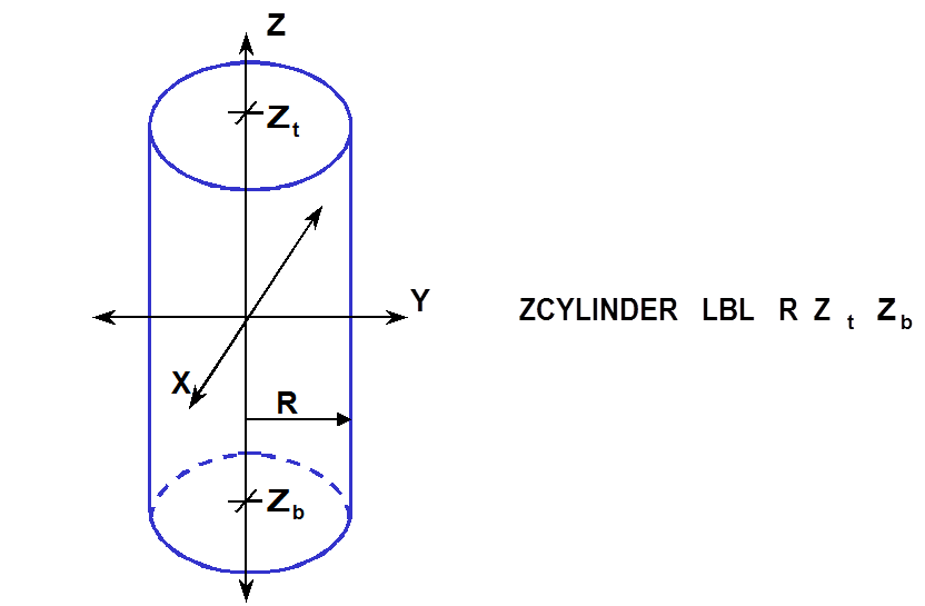
Fig. 8.1.231 Example of zcylinder construction.
- ZPPLANE
is a set of flat parallel surfaces where any two points in one of the surfaces can be connected by a straight line entirely contained within that surface. These surface planes divide space into three sections; one section between the two planes which is considered inside the surfaces, one section on the negative side of the negative plane which is considered outside the surfaces, and one section on the positive side of the positive plane which is considered outside the surfaces. The set of parallel planes are defined by the keyword ZPPLANE, which places the planes perpendicular to the Z-axis, the Z-intercept between the more positive plane and the Z-axis (Z+) and the Z-intercept between the more negative plane and the Z-axis (Z-). Fig. 8.1.232 shows the correct input sequence for the set of paired planes.
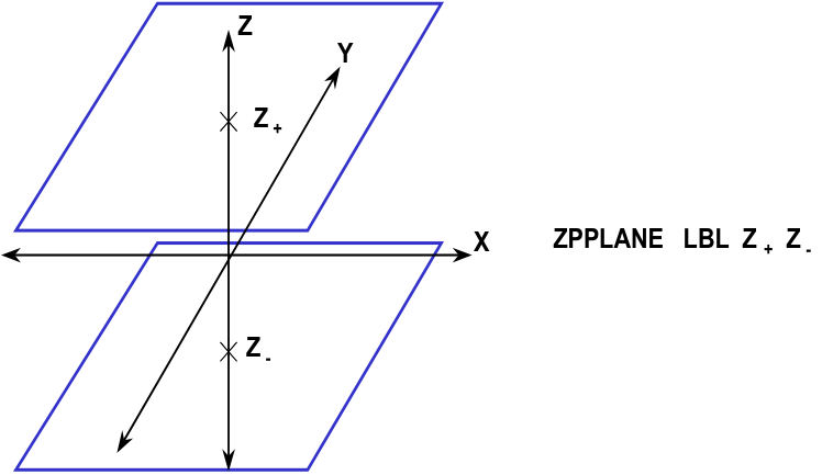
Fig. 8.1.232 Example of z-paired plane construction.